The 5% Rule: Why Your Long Cable Runs Are Failing CEC Inspection
That 150-metre cable run to the parking garage looked fine on paper. The wire was sized for ampacity. The breaker was correct. But the ESA inspector failed it anyway - because of voltage drop. Here's the rule every engineer needs to master.
What CEC Rule 8-102 Actually Says
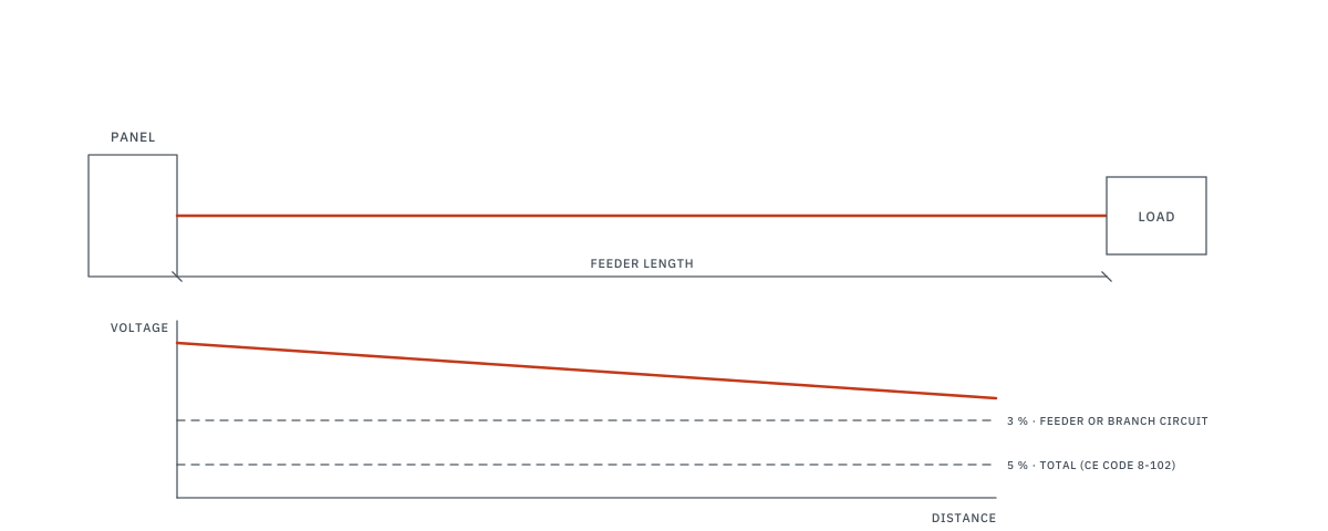
The Canadian Electrical Code, Rule 8-102, states that voltage drop shall not exceed 3% in a feeder or branch circuit and 5% total from the supply side of the service to the point of utilization. This is not a suggestion - it is a code limit that ESA inspectors can enforce.
CEC Rule 8-102: Voltage drop shall not exceed 3% in a feeder or branch circuit and shall not exceed 5% from the supply side of the consumer's service to the point of utilization.
At the 5% overall limit, that's a maximum of 6V for a 120V circuit, 10.4V for 208V and 17.35V for 347V; a single feeder or branch circuit is limited to 3% (3.6V, 6.24V and 10.41V).
The common 3% feeder / 2% branch split is a practical design target, but the code language itself limits each feeder or branch circuit to 3% and the overall installation to 5%.
The Voltage Drop Formulas
For copper conductors in steel conduit (most common commercial installation):
Single Phase:
VD = 2 × I × L × R / 1000
Three Phase:
VD = √3 × I × L × R / 1000
Where: I = current (A), L = one-way length (m), R = conductor resistance (Ω/km)
Conductor Resistance Table (Copper, 75°C)
| Wire Size (AWG/kcmil) | Approximate AC resistance (resistance-only method; reactance neglected), Ω/km |
Typical Ampacity (75°C) | |
|---|---|---|---|
| Steel Conduit | Non-metallic | ||
| #14 | 10.2 | 10.2 | 15A |
| #12 | 6.50 | 6.50 | 20A |
| #10 | 4.07 | 4.07 | 30A |
| #8 | 2.56 | 2.56 | 50A |
| #6 | 1.61 | 1.61 | 65A |
| #4 | 1.02 | 1.02 | 85A |
| #3 | 0.810 | 0.810 | 100A |
| #2 | 0.656 | 0.643 | 115A |
| #1 | 0.524 | 0.510 | 130A |
| 1/0 | 0.420 | 0.404 | 150A |
| 2/0 | 0.335 | 0.321 | 175A |
| 3/0 | 0.269 | 0.254 | 200A |
| 4/0 | 0.217 | 0.203 | 230A |
| 250 kcmil | 0.187 | 0.171 | 255A |
| 350 kcmil | 0.138 | 0.125 | 310A |
| 500 kcmil | 0.105 | 0.0902 | 380A |
The resistance values are approximate AC resistances for the resistance-only formulas above; reactance is neglected.
Worked Example: Parking Garage EV Panel
You're feeding a 100A, 208V, 3-phase EV charging panel located 150 metres from the electrical room. The engineer specifies #1 AWG copper in steel conduit.
Step 1: Calculate Voltage Drop
VD = √3 × 100A × 150m × 0.524 Ω/km / 1000
VD = 1.732 × 100 × 150 × 0.000524
VD = 13.6V
Step 2: Check Against the 3% and 5% Limits
Maximum allowed VD = 208V × 3% = 6.24V (feeder); 208V × 5% = 10.4V (overall)
Calculated VD = 13.6V - FAILS (6.5%)
Step 3: Upsize the Conductor
Try 4/0 AWG copper:
VD = 1.732 × 100 × 150 × 0.000217 = 5.64V (2.7%) - PASSES the 3% feeder limit
Notice the gap: #1 AWG has plenty of ampacity for 100A (rated 130A), but fails on voltage drop. This is the classic trap - the wire is big enough to carry the current safely, but the voltage arriving at the load is too low for equipment to operate properly.
When Voltage Drop Matters Most
- Underground parking garages: Long horizontal runs from the electrical room to the far end of the garage
- Site lighting circuits: Parking lot poles 200+ metres from the panel on 347V circuits
- Motor loads: Pumps, fans, and compressors in mechanical penthouses or remote buildings
- Construction power: Temporary panels fed by long cable runs across job sites
Common Mistakes
- Sizing wire for ampacity only - the wire may carry the current safely but deliver insufficient voltage
- Using DC resistance instead of AC resistance - AC resistance in steel conduit is higher due to skin effect and conduit losses
- Forgetting the return path for single-phase - use the one-way length L; the "2" factor in the formula accounts for the return path
- Not accounting for temperature derating - resistance increases with temperature; a hot conduit run has higher voltage drop
Frequently Asked Questions
What is the maximum voltage drop per CEC?
CEC/OESC Rule 8-102: max 3% in a feeder or branch circuit and max 5% total from service to point of utilization. See our load calculation guide for demand calculations.
How do you calculate voltage drop?
Single-phase: Vd = 2 × I × R × L / 1000. Three-phase: Vd = √3 × I × R × L / 1000. Then size the raceway using CEC conduit fill tables.
When does voltage drop matter most?
Long runs (parking garages, EV chargers), motor loads, sensitive electronics, and lighting circuits where dimming is visible.