Conduit Fill & Raceway Sizing: CEC Table 8 Explained
Oversized conduit wastes material. Undersized conduit fails inspection and damages wire insulation during pulling. CEC Table 8 defines the maximum fill - here's how to use it correctly.
CEC Rule 12-910: Maximum Conduit Fill
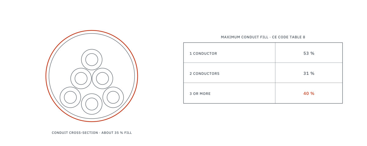
The CEC limits the percentage of a conduit's internal cross-sectional area that can be occupied by conductors:
| Number of Conductors | Maximum Fill (%) | Rationale |
|---|---|---|
| 1 conductor | 53% | Single conductor fills half the conduit - easy pull |
| 2 conductors | 31% | Two wires jam more easily - reduced fill |
| 3 or more | 40% | Standard multi-conductor fill - most common scenario |
Why not 100%? Conductors need space to dissipate heat. Overfilling causes higher operating temperatures, insulation degradation, derating, and potential fire hazard. The fill percentages also allow for practical wire pulling without damaging insulation.
Conduit Types Comparison
| Type | Trade Name | Use | Internal Area (1") |
|---|---|---|---|
| EMT | Electrical Metallic Tubing | Indoor dry locations, most common commercial | ≈ 557 mm² |
| Rigid | Rigid Metal Conduit (RMC) | Exposed, outdoor, industrial - heavy duty | ≈ 572 mm² |
| PVC | PVC Rigid Conduit | Underground, corrosive environments | ≈ 537 mm² |
| Flex | Flexible Metal Conduit | Equipment connections, vibration isolation | Varies - see CEC Tables 9A–9P |
| LFMC | Liquid-Tight Flexible | Wet locations, rooftop equipment, A/C units | Varies - see CEC Tables 9A–9P |
Step-by-Step Conduit Sizing
- 1. List all conductors - size, type (T90 Nylon, TECK, RW90), including grounds and bonding
- 2. Look up conductor area - CEC Table 10 gives cross-sectional area (mm²) for each conductor including insulation
- 3. Sum total conductor area - add all conductor areas together
- 4. Determine fill percentage - 53% (1 wire), 31% (2 wires), or 40% (3+ wires)
- 5. Select conduit - CEC Tables 9A–9P give the allowable area for each conduit size and type at each fill percentage. Choose the smallest conduit where allowable area ≥ total conductor area
Quick Reference: Common Scenarios
| Circuit | Conductors (T90 Nylon) | Total Area | Min EMT Size |
|---|---|---|---|
| 15A lighting circuit | 2 × #14 + 1 × #14 bond | ~18 mm² | 1/2" (trade 16) |
| 20A receptacle circuit | 2 × #12 + 1 × #12 bond | ~26 mm² | 1/2" (trade 16) |
| 3Φ motor branch (30A) | 3 × #10 + 1 × #10 bond | ~53 mm² | 1/2" (trade 16) |
| 100A feeder | 3 × #3 + 1 × #6 bond | ~211 mm² | 1-1/4" (trade 35) |
| 200A feeder | 3 × 3/0 + 1 × #4 bond | ~523 mm² | 2" (trade 53) |
| 400A feeder | 3 × 500kcmil + 1 × #2 bond | ~1,373 mm² | 2-1/2" (trade 63) |
Total areas: π × (OD/2)² from the nominal diameters of stranded copper T90 Nylon/TWN75 in General Cable (Prysmian) SPEC 5490, T90 High Speed. Min EMT is the smallest trade size whose 40 % fill area (nominal inside diameter) holds the total, except for the 100A and 200A rows, which show one size larger: their fill-based minimum (trade 27 and trade 41) uses 95 % and 99.5 % of that area and leaves no pulling margin. Diameters vary by manufacturer, so check the actual conductor.
Common Mistakes
| Mistake | Why It's Wrong | Correct Approach |
|---|---|---|
| Forgetting the bonding conductor | Bond conductor counts toward fill - can push you to the next conduit size | Always include the bonding/grounding conductor in area calculations |
| Mixing conductor types | Different insulation types have different diameters - can't use "all same size" tables | Calculate area individually for each conductor type |
| Using 40% fill for 2 conductors | 2 conductors = 31% max, not 40% | Check conductor count first, then apply correct fill percentage |
| Not accounting for cable vs conductor | Cables (NMD90, TECK) use outer diameter, not individual conductor area | Use cable OD to calculate area: π × (OD/2)² |
| Ignoring pull tension on long runs | >30m runs or multiple bends may need upsizing even if fill is technically OK | Keep long runs to two 90° bends between pull points where practical (the code allows more), or upsize the conduit |
Derating When Conduits Are Full
When many current-carrying conductors share a conduit, ampacity derating applies per CEC Table 5C:
| Current-Carrying Conductors | Derating Factor |
|---|---|
| 1-3 | 100% (no derating) |
| 4-6 | 80% |
| 7-24 | 70% |
| 25-42 | 60% |
| 43+ | 50% |
Neutral conductors carrying only unbalanced current are not counted as current-carrying. However, neutrals carrying harmonic currents (3rd harmonic from non-linear loads like LEDs) must be counted.
Frequently Asked Questions
What is the maximum conduit fill?
CEC Rule 12-910: 53% for 1 conductor, 31% for 2, 40% for 3+. Always calculate using conductor OD including insulation.
How do I size conduit for multiple wires?
Sum conductor areas, divide by 40% (for 3+ wires), select conduit with sufficient internal area. Check voltage drop for long runs.
Does conduit fill affect ampacity?
Yes. More than 3 current-carrying conductors require ampacity derating per CEC Table 5C: 4-6 wires = 80%, 7-24 = 70%.