Designing Tier III Data Centers: The Electrical Architecture Behind 99.982% Uptime
When a significant outage can cost over $1 million (Uptime Institute, 2025), the electrical design isn't just engineering - it's risk management. Here's how Tier III data center architectures achieve concurrently maintainable power systems. The 99.982% availability (less than 1.6 hours of downtime per year) often quoted for Tier III is a commonly cited figure, not part of the Uptime Institute Tier Standard.
Understanding Tier Classifications
The Uptime Institute's Tier Standard defines four levels of data center infrastructure reliability. Each tier builds on the one below it, adding redundancy and fault tolerance. The availability rows below are indicative only, not part of the Tier definitions or a guarantee; the electrical engineer's job is to translate reliability targets into concrete power distribution architectures.
| Parameter | Tier I | Tier II | Tier III | Tier IV |
|---|---|---|---|---|
| Availability | 99.671% | 99.741% | 99.982% | 99.995% |
| Annual Downtime | 28.8 hrs | 22.7 hrs | 1.6 hrs | 0.4 hrs |
| Power Path | Single | Single + redundant | Multiple active | Multiple active |
| UPS Redundancy | N | N+1 | N+1 (dual bus) | 2N or 2(N+1) |
| Concurrently Maintainable | No | No | Yes | Yes |
| Fault Tolerant | No | No | No | Yes |
| Typical Application | Small business | SMB, branch office | Enterprise, cloud | Banking, gov't |
"Concurrently maintainable" means every component in the power and cooling path can be shut down for planned maintenance without affecting IT operations. This is the defining characteristic of Tier III - and the single biggest driver of electrical design complexity.
UPS Topology: The Heart of the Design
The Uninterruptible Power Supply is the centerpiece of data center electrical architecture. Three primary topologies are used in modern facilities:
| Topology | How It Works | Efficiency | Protection Level | Best For |
|---|---|---|---|---|
| Standby (Offline) | Switches to battery on failure | 95-98% | Basic | Desktop PCs, home office |
| Line-Interactive | Voltage regulation + battery | 95-97% | Moderate | Network closets, small servers |
| Double Conversion (Online) | Continuous AC-DC-AC conversion | 90-96% | Maximum | Data centers, mission-critical |
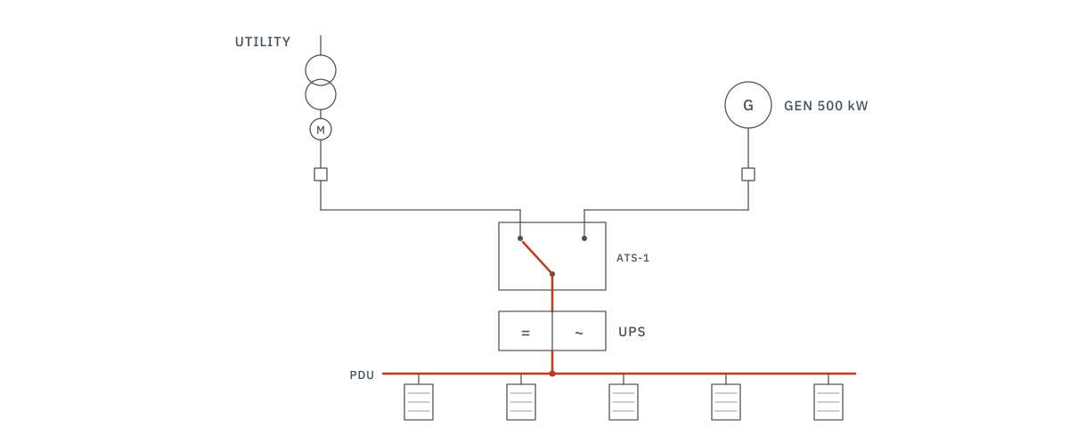
For Tier III and above, double-conversion online UPS is the standard. The continuous conversion isolates the IT load from all utility power anomalies - sags, swells, harmonics, frequency variations, and transients are completely eliminated.
Power Distribution Architectures
N+1 vs. 2N: What's the Difference?
These terms describe how much redundancy exists in the power system:
- N: The minimum capacity needed to run the full IT load - no redundancy
- N+1: One extra module beyond minimum - if a 500 kVA load requires two 300 kVA UPS modules, you install three. Any single module can be taken offline for maintenance
- 2N: Completely duplicated power path - two independent UPS systems, each capable of carrying the full load. The IT equipment has dual power supplies connected to separate buses
- 2(N+1): Two complete systems, each with internal redundancy - the pinnacle of availability for Tier IV
PUE: Measuring Efficiency
Power Usage Effectiveness (PUE) is the industry-standard metric for data center energy efficiency:
PUE Formula:
PUE = Total Facility Power / IT Equipment Power
A PUE of 1.0 means all power goes to IT. Industry average is ~1.58. Best-in-class hyperscalers achieve 1.1-1.2.
| PUE Range | Efficiency Rating | Where You Typically See This |
|---|---|---|
| 1.0-1.2 | Exceptional | Hyperscale (Google, Meta), purpose-built facilities |
| 1.2-1.4 | Good | Modern colocation, well-designed enterprise |
| 1.4-1.6 | Average | Typical enterprise, retrofitted facilities |
| 1.6-2.0 | Below Average | Legacy facilities, poor cooling design |
| > 2.0 | Inefficient | Converted office space, no containment |
The AI/HPC Power Density Challenge
Traditional data centers were designed for 5-8 kW per rack. AI training clusters running NVIDIA H100 or B200 GPUs now demand 40-100+ kW per rack. This fundamentally changes the electrical design:
- Busway distribution replaces traditional cable trays - higher capacity in less space
- Liquid cooling becomes mandatory - air cooling simply cannot handle 100 kW rack densities
- Utility coordination is critical - a single AI cluster can require 5-20 MW, rivaling small industrial plants
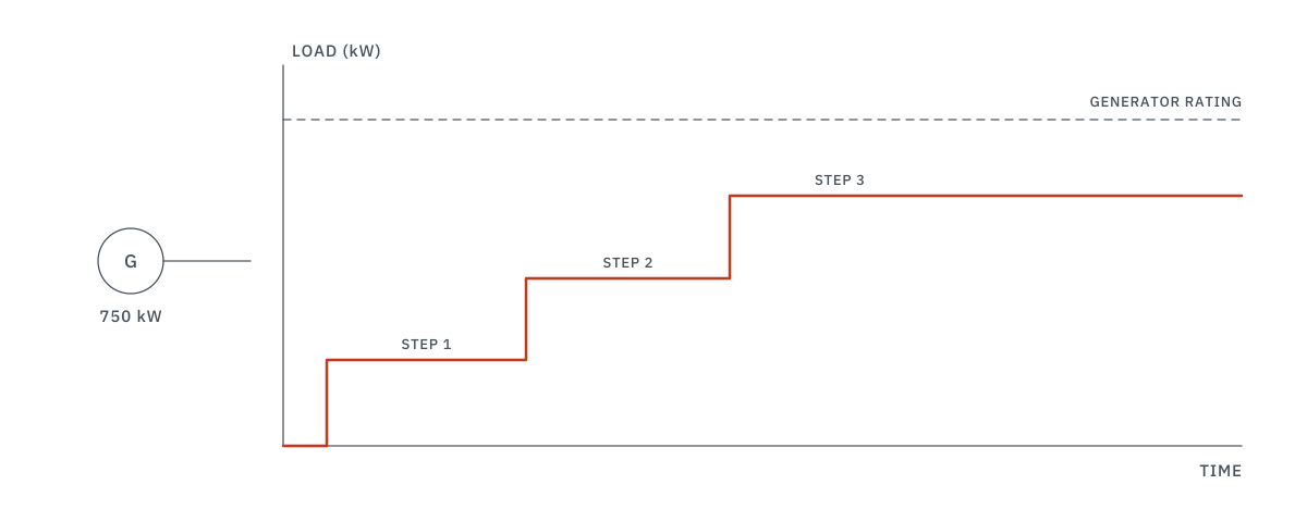
- Step-loading analysis is essential - GPU clusters have extreme inrush characteristics that affect generator and UPS sizing
Common Design Mistakes
- Oversizing UPS for day-one load - UPS modules operate most efficiently at 40-70% load. Massive oversizing wastes energy 24/7
- Ignoring harmonic distortion - IT switch-mode power supplies generate significant harmonics that derate transformers and cables
- Single-corded servers on a 2N system - the most expensive power architecture is wasted if servers only have one power supply
- No metering at the PDU level - you can't optimize what you don't measure. Branch circuit monitoring is essential for capacity management
Frequently Asked Questions
What is a Tier III data center?
N+1 redundancy, concurrently maintainable; 99.982% uptime is a commonly cited figure, not part of the Uptime Institute Tier Standard. Dual power paths, redundant UPS. See our ATS design guide.
What is PUE?
Power Usage Effectiveness = Total Power / IT Power. Industry avg: 1.58. Best-in-class: 1.1-1.2.
Best UPS for data centers?
Double-conversion online UPS. Zero transfer time, complete utility isolation. Modular for N+1 scaling.