VFD Cable Selection: Why Standard Cable Won't Work
It's one of the most costly specification mistakes in building electrical: running a standard T90 Nylon (THWN-type) wire from a VFD to a motor and wondering why the motor failed six months later. VFD output is not standard AC power - and the cable between a drive and its motor must be treated differently.
What Makes VFD Output Different?
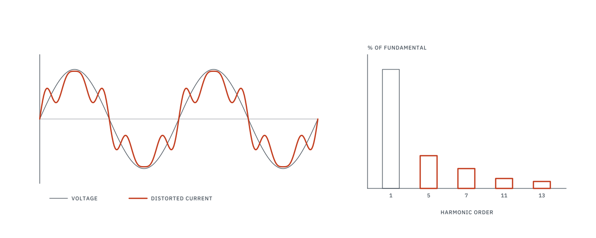
A Variable Frequency Drive (VFD) does not output smooth sinusoidal AC power. It outputs a series of rapid Pulse Width Modulated (PWM) voltage pulses - typically switching at 2,000 to 16,000 Hz. These high-frequency pulses create electrical stresses that standard cables were never designed to handle:
- High dV/dt (voltage rise rate) - voltage can spike from 0 to 650V in microseconds, stressing insulation
- Reflected wave phenomenon - voltage pulses reflect off the motor terminals at long cable runs, causing peak voltages of roughly twice the drive's DC bus voltage
- Common-mode currents - high-frequency currents flow through cable capacitance to ground, causing EMI interference
- Bearing currents - induced shaft voltages discharge through motor bearings, causing premature bearing failure
On longer cable runs, reflected-wave peaks at the motor terminals can approach twice the drive's DC bus voltage: roughly 1,200-1,400V on a 480V drive, and higher on the 575/600V drives common in Ontario. Standard building-wire insulation is rated 600V. The math doesn't work.
Why Standard THWN/THHN Cable Fails
Standard building wire (T90 Nylon/TWN75 in Canada; THWN/THHN in the US) is designed for 60Hz sinusoidal power. Its limitations in VFD applications:
| Issue | Standard T90 Nylon / THWN | VFD-Rated Cable |
|---|---|---|
| Insulation thickness | Standard (600V rated) | Thicker (1000V+ rated) |
| Insulation material | PVC/Nylon | XLPE or EPR (better dielectric) |
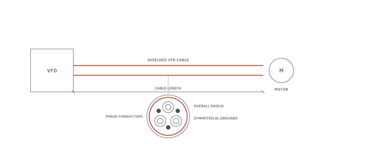
| Shielding | None | 100% braid or foil + drain wire |
| Ground conductors | 1 ground | Symmetrical 3-ground conductors |
| EMI containment | None | Shielded, reduces radiated noise |
| Reflected wave protection | None | Lower capacitance design |
| Expected lifespan (VFD) | Shortened (insulation breakdown) | Designed for VFD service |
When is VFD-Rated Cable Required?
Always Recommended (Output Side)
Between the VFD output terminals and the motor - follow the drive manufacturer's cable requirements, which in practice call for VFD-rated cable here. This is the high-stress portion of the circuit. The cable should be rated for:
- 1,000V minimum (to handle reflected wave peaks)
- 100% shielding (braid or foil, bonded at both ends)
- Symmetrical ground conductors (minimizes common-mode inductance)
Input Side (VFD Line Side)
The input side (utility/panel to VFD) sees standard 60Hz power - standard THWN is generally acceptable here. However, if the VFD is near sensitive electronic equipment, shielded cable on the input side can reduce conducted EMI on the building's electrical system.
The Cable Run Length Problem
The reflected wave voltage peak increases with cable length. Limits depend on the drive, the motor's insulation rating and the cable - for older 1,000V-insulation motors they can be well under 30m. Follow the drive manufacturer's lead-length tables; as a general guide only:
| Cable Run Length | Risk Level | Mitigation Required |
|---|---|---|
| Under 30m | Low | VFD-rated cable sufficient |
| 30m - 60m | Moderate | VFD cable + output reactor or dV/dt filter |
| 60m - 150m | High | VFD cable + sine wave filter recommended |
| Over 150m | Very High | Engineer review required - may need inverter-duty motor |
Inverter-Duty Motors
For long cable runs or high-cycle VFD applications, standard NEMA B motors may not suffice. Inverter-duty motors (NEMA MG-1 Part 31) are built to handle VFD-induced stresses:
- Reinforced winding insulation (Class F or H)
- Insulated bearings to block bearing currents
- Shaft grounding rings (on larger motors)
- Inverter-duty insulation per NEMA MG 1 Part 31; confirm the peak-voltage rating with the motor manufacturer
Motors installed in Ontario must also be certified for use in Canada (CSA C22.2 No. 100).
Practical Specification Checklist
When specifying a VFD installation, confirm:
- VFD-rated shielded cable on output side (always)
- Shield bonded to VFD ground and motor frame at both ends
- Cable run length reviewed against manufacturer limits
- Output reactor or filter specified where the run exceeds the drive manufacturer's lead-length limit
- Motor is inverter-duty rated (NEMA MG-1 Part 31) for critical applications
- Separate conduit from other power/control cables (EMI isolation)
Frequently Asked Questions
When do I need VFD-rated cable?
VFD-rated cable is recommended for all VFD-to-motor runs, and matters most on longer runs and on 575/600V drives. The safe length depends on the drive, the cable and the motor insulation, so follow the drive manufacturer's lead-length limits. The high dV/dt from PWM switching causes voltage reflections that damage standard insulation.
Can I use regular T90 Nylon (THWN) wire with a VFD?
Standard building wire lacks the shielding and insulation properties needed for VFD applications. It may be acceptable for short runs within the drive manufacturer's lead-length limits, but VFD-rated cable is the recommended practice. See our motor protection guide for related MCA/MOP sizing.
What is an inverter-duty motor?
An inverter-duty motor is designed per NEMA MG1 Part 31 to withstand the voltage spikes from VFD operation. It has reinforced inverter-duty insulation per NEMA MG 1 Part 31; confirm the peak-voltage rating with the motor manufacturer, and better bearing protection. See our HVAC coordination guide for VFD application in HVAC systems.